


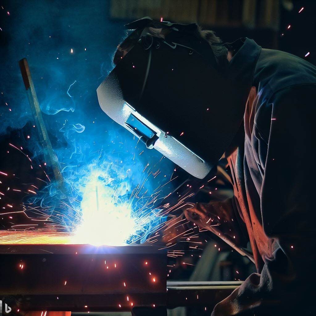
CNC Press Brake Forming Services
Precision Sheet Metal Bending for OEMs and Industrial Manufacturers
CNC press brake forming transforms flat sheet metal into precise three-dimensional components used in industrial equipment, automation systems, machine guards, electrical enclosures, structural assemblies, material handling equipment, and OEM products. At METCO Metal Fab, forming is tightly integrated with fiber laser cutting, machining, welding, hardware installation, and assembly support to provide complete fabrication solutions.

Whether you need a prototype bracket, a complex enclosure, or repeat production quantities, successful forming depends on far more than tonnage. Material selection, bend radius, springback, tooling, flat-pattern development, and manufacturability all influence the final result. Successful forming starts with manufacturable design, accurate flat pattern development, and realistic tolerance requirements.
What Is CNC Press Brake Forming?
Press brake forming is a manufacturing process that bends sheet metal with a punch and die set controlled by a CNC press brake. A laser-cut blank is positioned against a programmable backgauge before the machine applies precisely controlled force to create the required geometry.
Manufacturers use CNC press brake forming to produce brackets, channels, conveyor components, electrical enclosure components, structural supports, weldment details, and complex multi-bend OEM parts. Because the process creates strength through geometry, engineers can often reduce weight while maintaining structural performance.

For example, a properly designed flange can increase rigidity, reduce welding requirements, simplify assembly, and lower overall manufacturing cost. As a result, many formed components achieve the required strength without thicker material or additional reinforcement.
Contact METCO to discuss your forming requirements→
METCO’s AMADA HRB2204 Press Brake Capabilities
The AMADA HRB2204 supports a wide range of CNC press brake forming applications. The machine routinely produces long channels, machine guards, heavy-gauge components, multi-bend production parts, hemmed features, offset bends, acute bends, and return flanges.
Additionally, the 243-ton platform can form parts up to 14 feet long while maintaining excellent repeatability. The multi-axis backgauge and AMNC 3i control system help operators achieve consistent dimensions across prototype and production quantities.
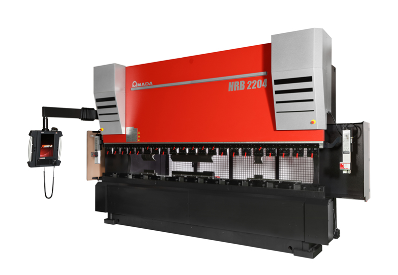
Whether a project requires a simple bracket or a complex formed assembly, the HRB2204 provides the flexibility needed for modern sheet metal manufacturing.
Contact METCO to discuss your forming requirements→
How CNC Press Brake Forming Works
Most CNC press brake forming projects begin with a fiber laser cut blank. During setup, the operator positions the blank against the programmable backgauge, which locates the bend line with precision. The press brake then drives a punch into the selected die opening to generate the desired bend angle.
Meanwhile, the CNC controller manages critical variables such as bend sequence planning, backgauge positioning, tonnage requirements, die selection, springback compensation, and angle correction. Consequently, the machine produces repeatable bends that support consistent production quality and improved assembly fit.
Materials Commonly Formed at METCO
Carbon Steel
A36 and A1011 are widely used for formed components, with A1011 generally providing more consistent forming characteristics.
Stainless Steel
304 and 316 stainless are frequently used where corrosion resistance is required. These materials require higher forming forces and exhibit greater springback than carbon steel.
Aluminum
Common alloys include 5052-H32 and 6061-T6. While aluminum reduces weight and improves corrosion resistance, alloy selection significantly affects formability. 5052 generally forms easily, while 6061-T6 requires greater attention to bend radius and grain direction.
Air Bending vs. Bottom Bending
Air Bending
The most common production method. The material contacts only the punch tip and die shoulders.
Advantages:
- Lowest tonnage
- Fast setup
- Flexible angle control
- Lower tooling costs
Disadvantages:
- Springback compensation required
- Radius influenced by material and die opening
Bottom Bending
Advantages:
- Improved angular accuracy
- Reduced springback
- Better repeatability
Disadvantages:
- Higher tonnage requirements
- Increased tooling wear
Most industrial work at METCO utilizes air bending because it provides the best balance of flexibility, repeatability, and economics.
Bend Radius Fundamentals
Inside bend radius directly affects cracking risk, springback, tooling selection, flat-pattern development, and cost. For materials susceptible to cracking, bends are generally more forgiving when made perpendicular to rolling direction rather than parallel to grain.
Recommended Starting Radii for General Production Work
| Material | Recommended Radius |
|---|---|
| A36 Steel | 1T |
| A1011 Steel | 1T |
| 304 Stainless | 1T to 1.5T |
| 316 Stainless | 1.5T |
| 5052-H32 Aluminum | 1T |
| 6061-T6 Aluminum | 2T to 4T |
T = Material Thickness
A common mistake is specifying the smallest possible radius. In many cases, a larger radius improves formability, reduces cracking risk, and lowers manufacturing cost.
Springback and Compensation
Springback occurs when metal attempts to return toward its original shape after forming. Every common sheet metal material exhibits some level of springback, although the amount varies significantly by alloy, thickness, temper, and bend radius.
Therefore, successful CNC press brake forming requires compensation during programming and setup. Operators may use controlled overbending, material-specific bend libraries, test bends, tooling adjustments, CNC angle correction, and crowning compensation to achieve the target angle. Ultimately, accurate springback management improves dimensional consistency and reduces setup time.
Typical Springback Ranges
| Material | Typical Springback |
|---|---|
| Mild Steel | 1° to 2° |
| 304 Stainless | 2° to 4° |
| 5052 Aluminum | 2° to 3° |
| 6061-T6 Aluminum | 3° to 6° |
Bend Allowance, Bend Deduction, and K-Factor
Flat-pattern development is critical for accurate formed parts.
Bend Allowance
Bend allowance represents the material length consumed within the bend region. Incorrect bend allowance results in wrong flange dimensions and assembly issues.
Bend Deduction
Bend deduction calculates flat length by subtracting material from outside dimensions. While mathematically different, both methods can generate the same flat blank when applied correctly.
Common K-Factor Values
Typical starting K-factor assumptions used by many CAD systems:
| Material | Typical K-Factor |
|---|---|
| Mild Steel | 0.42 |
| Stainless Steel | 0.43 |
| 5052 Aluminum | 0.44 |
| 6061 Aluminum | 0.45 |
Actual production values should be validated through test bends or proven bend tables. Production-proven bend tables are often more valuable than theoretical calculations alone because they are based on actual material, tooling, and machine performance.
Minimum Flange Length Requirements
One of the most common DFM problems is designing a flange too short to be supported by the die during bending.
Practical Guidelines
A common starting guideline is a minimum flange length of approximately 4× material thickness, although actual requirements depend on die opening, tooling geometry, and material properties.
Preferred Flange Length = 6 × Material Thickness
Examples:
| Material Thickness | Minimum Flange Length |
|---|---|
| .125″ | .500″ |
| .250″ | 1.000″ |
Parts that violate these guidelines often require specialty tooling, additional setups, or design modifications.
Hole-to-Bend Distance Guidelines
Features located too close to a bend are susceptible to distortion, stretching, movement, and tearing.
One commonly used starting guideline is 2.5T + R, although actual requirements vary with material, bend angle, hole geometry, and forming method.
Where:
- T = Material Thickness
- R = Inside Bend Radius
Example:
Material Thickness = .125″
Inside Radius = .125″
Minimum Distance = (2.5 × .125) + .125 = .4375″
For this example, a hole should be located approximately 7/16 inch away from the bend line.
Bend Relief Design Guidelines
Bend reliefs provide room for material flow when bends terminate near edges.
Recommended starting guidelines:
- Relief Width = 1.5T minimum
- Relief Depth = Beyond bend tangent line
Benefits include:
- Reduced tearing
- Improved dimensional consistency
- Better cosmetic appearance
- Improved assembly fit
Ignoring bend reliefs is a common cause of corner cracking and deformation.
Forming Tolerances and Quality Assurance
Formed parts behave differently than machined parts because material is stretched and compressed during bending. Material thickness variation, yield strength variation, and springback all influence final dimensions.
Typical Production Expectations
| Feature | Typical Capability |
|---|---|
| Standard Forming | ±0.030″ |
| Moderate Precision | ±0.015″ |
| Tight Forming | ±0.010″ Tolerance capability depends on material type, thickness, bend orientation, feature location, and measurement method. |
| Standard Bend Angle | ±1° |
| Precision Bend Angle | ±0.5° Tolerance capability depends on material type, thickness, bend orientation, feature location, and measurement method. |
For most industrial fabrications, ±0.015″ to ±0.030″ and ±1° provide an excellent balance of manufacturability, quality, and cost.
Inspection Methods and Quality Control
Inspection begins with a review of the customer drawing, GD&T requirements, and first article expectations. Throughout production, quality personnel verify dimensions, bend angles, hole locations, and critical features to ensure compliance with customer requirements.
METCO uses digital calipers, height gauges, angle finders, radius gauges, precision protractors, and inspection fixtures when a project requires additional verification.
Likewise, quality assurance extends beyond measurement. Material verification, tooling verification, program validation, first article inspection, and in-process inspection help maintain process control throughout production. Rather than relying on final inspection alone, the objective is to build quality into every stage of manufacturing.
Common Forming Problems and Solutions
Cracking
Usually caused by tight bend radii, unfavorable grain direction, or low-ductility materials.
Recommended Solution: Increase radius, review grain direction, and evaluate alternative materials.
Hole Distortion
Occurs when features are located inside the deformation zone.
Recommended Solution: Follow hole-to-bend spacing guidelines.
Wrong Flat Pattern
Typically caused by incorrect bend deductions, K-factors, or bend radius assumptions.
Recommended Solution: Use validated bend data and perform first article verification.
Twist and Warp
Often caused by asymmetrical geometry or improper bend sequencing.
Recommended Solution: Review design and forming strategy during the quoting stage.
Angle Variation
Can result from material property variations, die selection, tooling wear, or springback differences.
Recommended Solution: Use test bends and material-specific forming data.
Design for Manufacturability Recommendations
Parts that form successfully in production generally share several characteristics:
- Standard bend radii
- Adequate hole-to-bend spacing
- Realistic tolerances
- Bend reliefs where required
- Proper grain orientation
- Logical bend sequencing
- Sufficient flange length
Common design mistakes include:
- Holes too close to bends
- Radius smaller than material thickness
- Missing bend reliefs
- Overly restrictive tolerances
- Excessive bend counts
- Failure to consider tooling access
Tooling Access Considerations
The most manufacturable designs balance functional requirements with forming constraints, tooling access, and production efficiency.
The Amada SRB2204 press brake provides significant bending capacity and precision, but like any press brake, successful part production depends heavily on how a component is designed. Features such as deep returns, boxed sections, and narrow channels can introduce tooling and access limitations that affect manufacturability, setup time, and cost.
One of the most common issues is tooling access. A bend may look simple in CAD, but if the punch or die cannot physically reach the bend location without interference, the part may require specialty tooling or redesign. This becomes increasingly important when bends are positioned close to sidewalls, tabs, gussets, or previously formed features. The SRB2204’s precision backgauging helps maintain accuracy, but proper tool access must still exist throughout the forming process.
Box forming and Deep Return Flanges
Box forming limitations are another consideration. As sidewalls become taller, the risk of the formed walls colliding with the press brake frame, tooling, or ram increases. Closed or partially enclosed box geometries often require staged forming sequences, specialized punches, or segmented tooling. In some cases, a design that appears straightforward may be impossible to form as a single-piece component without modifying flange heights or bend locations.
Designers should also pay close attention to return flanges. Return bends create additional stiffness and improve safety by eliminating exposed edges, but they can quickly create clearance issues. Small return flanges may not provide enough room for standard punch tooling, while larger returns can interfere with subsequent bends. Determining the proper flange length and bend sequence early helps avoid costly production adjustments.
Channel Forming Challenges
Similarly, deep channels present unique forming challenges. Narrow U-shaped profiles often require high-aspect-ratio tooling to reach the bottom of the channel. As depth increases relative to width, the risk of punch interference grows. Deep channels may also limit the order in which bends can be performed, especially when multiple flanges are located within the channel geometry.
Successful production relies heavily on collision avoidance. Modern press brake programming helps identify potential crashes between tooling, the machine, and the workpiece before forming begins. However, collision-free forming still depends on part geometry, tooling selection, and operator access. A design that cannot be safely manipulated during forming may require changes even if it appears theoretically manufacturable.
Collision Avoidance and Bend Sequencing
Finally, sequencing constraints often determine whether a part can be produced efficiently. Every bend changes how the workpiece interacts with the tooling. Certain features must be formed first to maintain access for later operations. When sequencing is overlooked during design, parts may require additional setups, specialty tooling, or even complete redesigns. Evaluating bend order during the design stage helps ensure the SRB2204 can produce parts consistently, accurately, and economically.
Understanding these forming constraints early in the design process reduces manufacturing risk, shortens lead times, and results in parts that are easier and more cost-effective to fabricate.
RFQ Preparation Guidance
Complete RFQs quote faster and produce fewer engineering questions.
Recommended RFQ package:
- PDF drawing
- STEP file or CAD model
- Material specification
- Material thickness
- Revision level
- Production quantities
- Finish requirements
- Hardware requirements
- Delivery requirements
- Critical dimensions
Providing complete information helps fabricators evaluate manufacturability, tooling requirements, quality expectations, and production strategy before quoting.
Cost Reduction Opportunities
The largest manufacturing savings often come from improved design rather than lower material costs. Designers can reduce cost by eliminating unnecessary bends, increasing bend radii when function allows, selecting more formable materials, and designing around standard tooling.
Beyond that, improved hole-to-bend spacing, realistic tolerances, and formed features that replace welded assemblies frequently reduce labor and setup time. In many situations, a single formed component can replace multiple welded pieces, resulting in fewer operations and improved consistency.
Consider a flat plate that requires welded angle reinforcement. Increasing material thickness may add weight, while continued welding increases labor. By contrast, adding a properly designed formed flange can increase stiffness, eliminate welding, reduce distortion, and lower total manufacturing cost.
Industries Served
METCO supports OEMs and industrial manufacturers across a broad range of industries. Customers include manufacturers of material handling equipment, industrial machinery, automation systems, control consoles, electrical enclosures, construction equipment, agricultural equipment, and food processing equipment.
Furthermore, the company provides CNC press brake forming services for general industrial fabrication projects that require prototype development, replacement parts, or recurring production runs. From concept through manufacturing, customers receive support focused on manufacturability, quality, and production efficiency.
Frequently Asked Questions
Can You Hold ±0.005″ On Formed Parts?
Sometimes, but not always economically. Material variation and springback make universal ±0.005″ tolerances impractical for many formed parts.
Why Does 6061-T6 Crack More Than 5052?
6061-T6 has lower formability, higher springback, and greater sensitivity to bend radius and grain direction.
Why Are Exact Bend Radii Difficult to Hold?
In air bending, die opening, material thickness, and material properties largely determine the resulting radius.
Why Does Grain Direction Matter?
Bending parallel to grain increases crack risk, particularly in stainless steel and 6061-T6 aluminum.
Why Is First Article Inspection Important?
It verifies dimensions, hole locations, bend angles, material behavior, and assembly fit before full production begins.
Can a Formed Part Replace a Welded Assembly?
Often, yes. Properly designed flanges can eliminate brackets, reinforcements, welds and lower cost.
Request a Quote
METCO combines fiber laser cutting, CNC press brake forming, machining, welding, PEM hardware installation, finishing, and assembly support into a single fabrication workflow. Whether you’re developing a prototype, transitioning a design into production, or looking to reduce manufacturing cost through Design for Manufacturability principles, our team can help.
Contact METCO Metal Fab today to discuss your CNC press brake forming requirements and request a manufacturability review and quotation.