


Design For Manufacturability (DFM) For Metal Fabrication
A part can function perfectly in CAD and still create costly manufacturing issues. DFM focuses on designing parts that a fabricator can build efficiently, consistently, and cost-effectively. When engineers consider manufacturing constraints early, they reduce risk throughout the entire project. Good DFM practice lowers production costs, reduces delays, and improves quality.
Written by Antony Sanchez, Sales Engineer
Oct 20, 2026
What Is Design for Manufacturability?
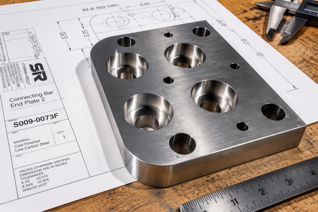
“Design for Manufacturability aligns engineering decisions with real-world fabrication processes. Instead of designing a part first and solving manufacturing issues later, DFM addresses those challenges during the design phase.”
Every design choice affects manufacturing. Material selection influences forming and welding. Hole locations affect bending operations. Tolerances determine inspection requirements. Assembly features impact labor costs.
As a result, a manufacturable design moves through production with fewer surprises.
Engineers often focus on function. Fabricators focus on repeatability. DFM brings both objectives together.
Why DFM Matters Before You Request a Quote
Many RFQs arrive with manufacturing challenges.
The design may look complete, yet several details can create problems once production begins. In many cases, these issues increase costs before the first part is ever built.
In Example: A laser cut hole placed too close to a bend may distort during forming. →
Likewise, an overly tight tolerance may require additional inspections and increase production cost unnecessarily.
Consequently, the fabricator must spend time reviewing the design, requesting clarification, or recommending revisions. These conversations slow the quoting process and create unnecessary engineering work.
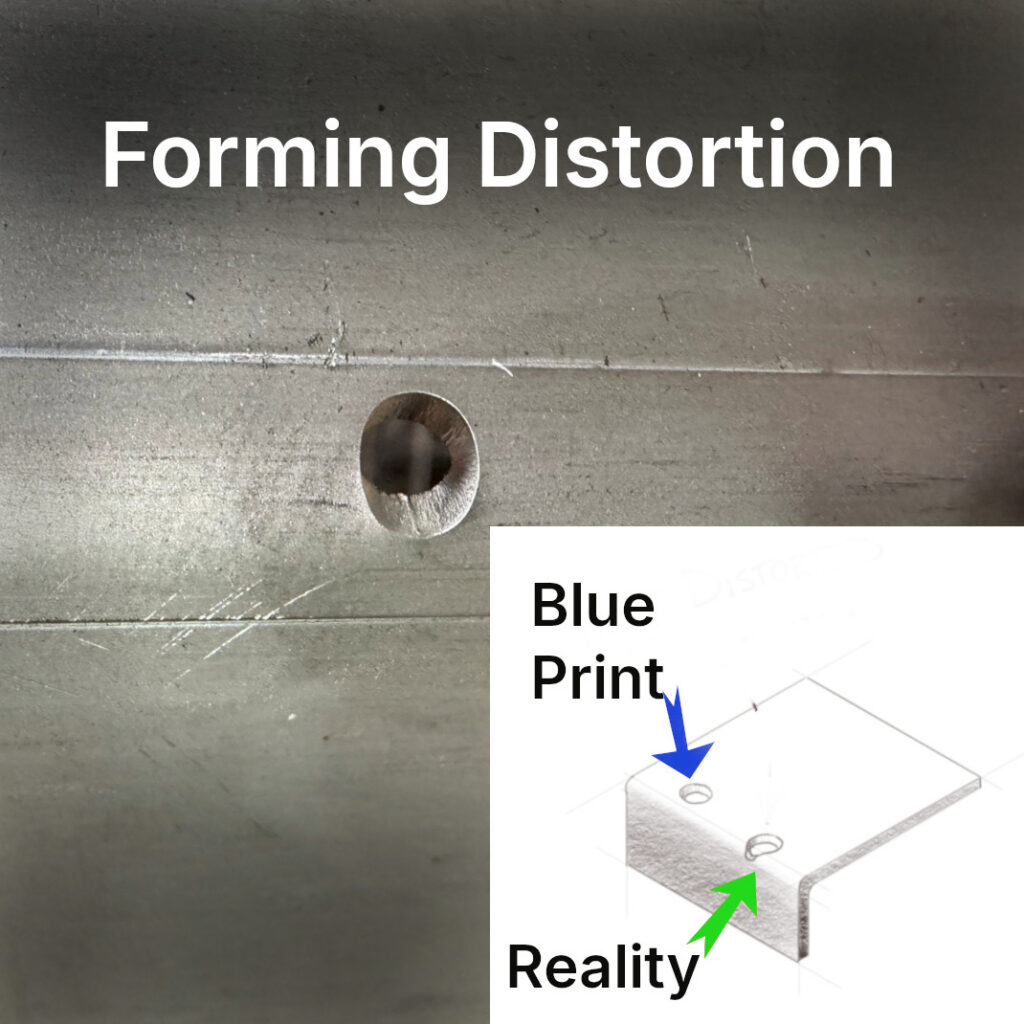
Not sure if your features are too close to a bend?
When manufacturability gets evaluated early, engineers avoid redesign cycles and buyers receive more accurate pricing. Typical starting points:
- A36 Steel: Inside Radius ≈ 1× Material Thickness
- 5052-H32 Aluminum and 304 Stainless: Inside Radius ≈ 1 – 1.5 × Thickness
- 6061-T6 Aluminum: Inside Radius ≈ 2-3× Thickness
Special Note on AR400 steel:
Most shops shy away from forming AR400 ($$$$) because it can shatter when not designed properly for forming. Mainly, one should use AR400F instead, because it was created with formability in mind. However, AR400F is not very common and can be difficult to source when spot buying a small quantity.
Proper hole-to-bend distance is one of the most common manufacturability challenges in sheet metal fabrication.
Learn more about hole placement. →
Recommended minimum hole-to-bend distance:
A common starting guideline is:
Minimum Hole-to-Bend Distance ≈ Hole Radius + Material Thickness + Inside Bend Radius
Actual requirements vary by material, tooling, and criticality.
f this requirement cannot be met, relief features or secondary machining may be required.
Free DFM Review
Before you release your drawing package, let us review it.
Our engineers routinely identify bend interference, hole placement issues, weld accessibility concerns, tolerance cost drivers, and hardware conflicts before production begins.
Engineering Feedback • Manufacturability Review
• Cost Reduction Opportunities • No Obligation
Fabrication Review Backed by Production Experience
METCO’s design recommendations are based on challenges we encounter every day in production. Because we laser cut, punch, form, machine, install hardware, weld, and assemble parts in-house, we routinely identify issues that may not be obvious during design.

Examples include PEM fasteners that become inaccessible after forming, channels that create tooling interference, weld joints with limited torch access, and tolerances that drive unnecessary inspection costs. Every recommendation is grounded in practical manufacturing experience, not theory alone.
Common findings during METCO DFM reviews include:
- Bend Radii that are too small and cause stress beyond Tensile Strength (ksi) for the material grade selected
- Deep channels that exceed practical press brake tooling clearance
- Hardware locations that interfere with forming operations
- Features that would benefit from turret punching instead of laser burning
- Weld joints that restrict operator access
- Tolerances tighter than required for assembly function
- Material selections that increase lead time without improving performance
Send a PDF or STEP file and we’ll identify potential manufacturing risks before production begins.
DFM Beyond Individual Parts
Many fabrication reviews focus on whether a single component can be manufactured. METCO evaluates how the component will move through the complete manufacturing process. A design decision that simplifies forming may complicate welding.
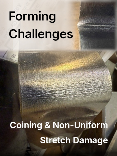
Have a Difficult Formed Part?
A feature that works well for laser cutting may require a creative solution at the press brake negating the cost advantage from reduced welding time. Reviewing the entire process helps uncover opportunities that individual process reviews often miss.
Identifying these issues before fabrication helps reduce labor, improve repeatability, and avoid costly revisions later in the project.
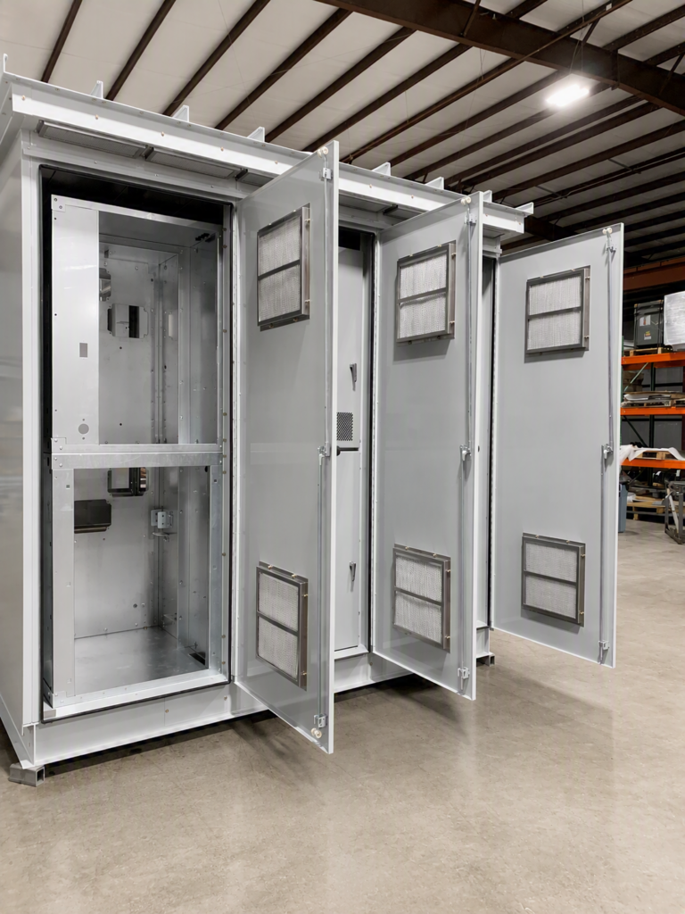
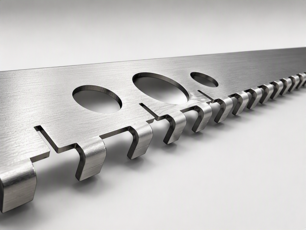
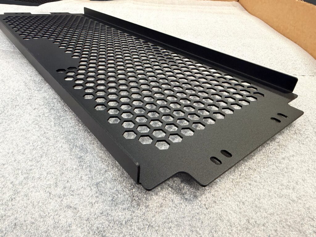


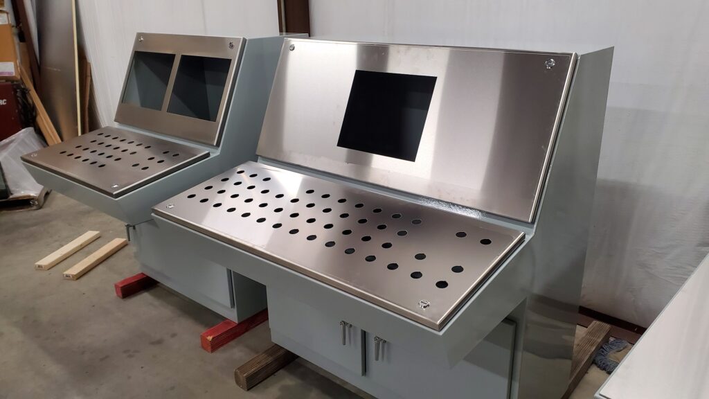


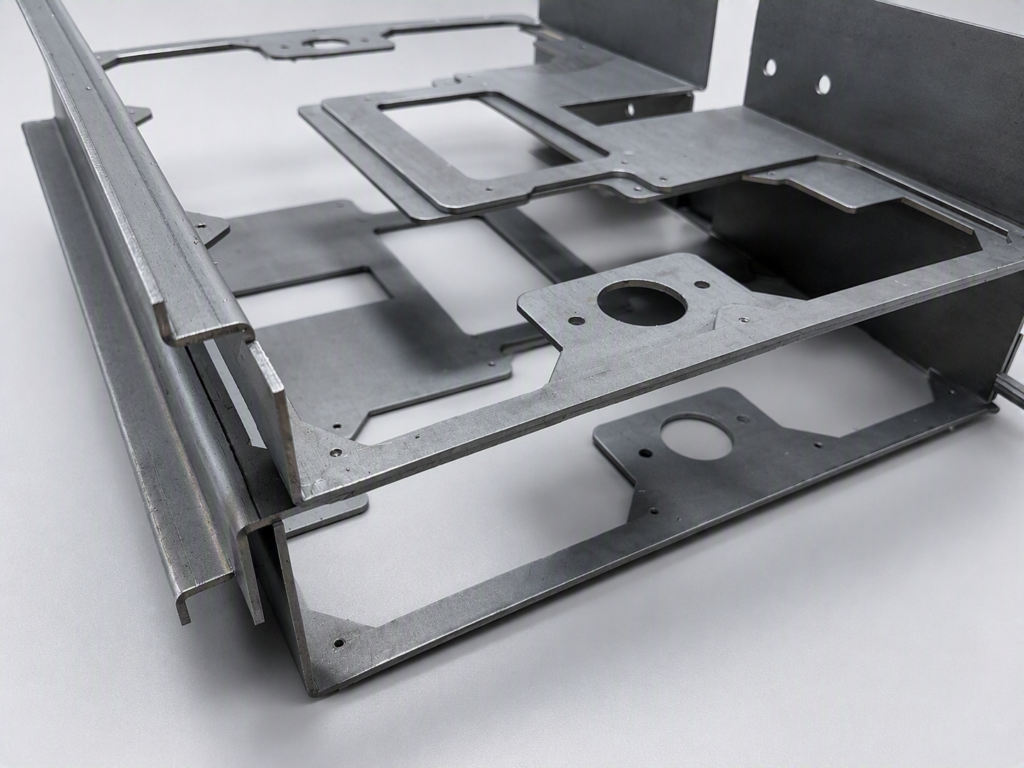
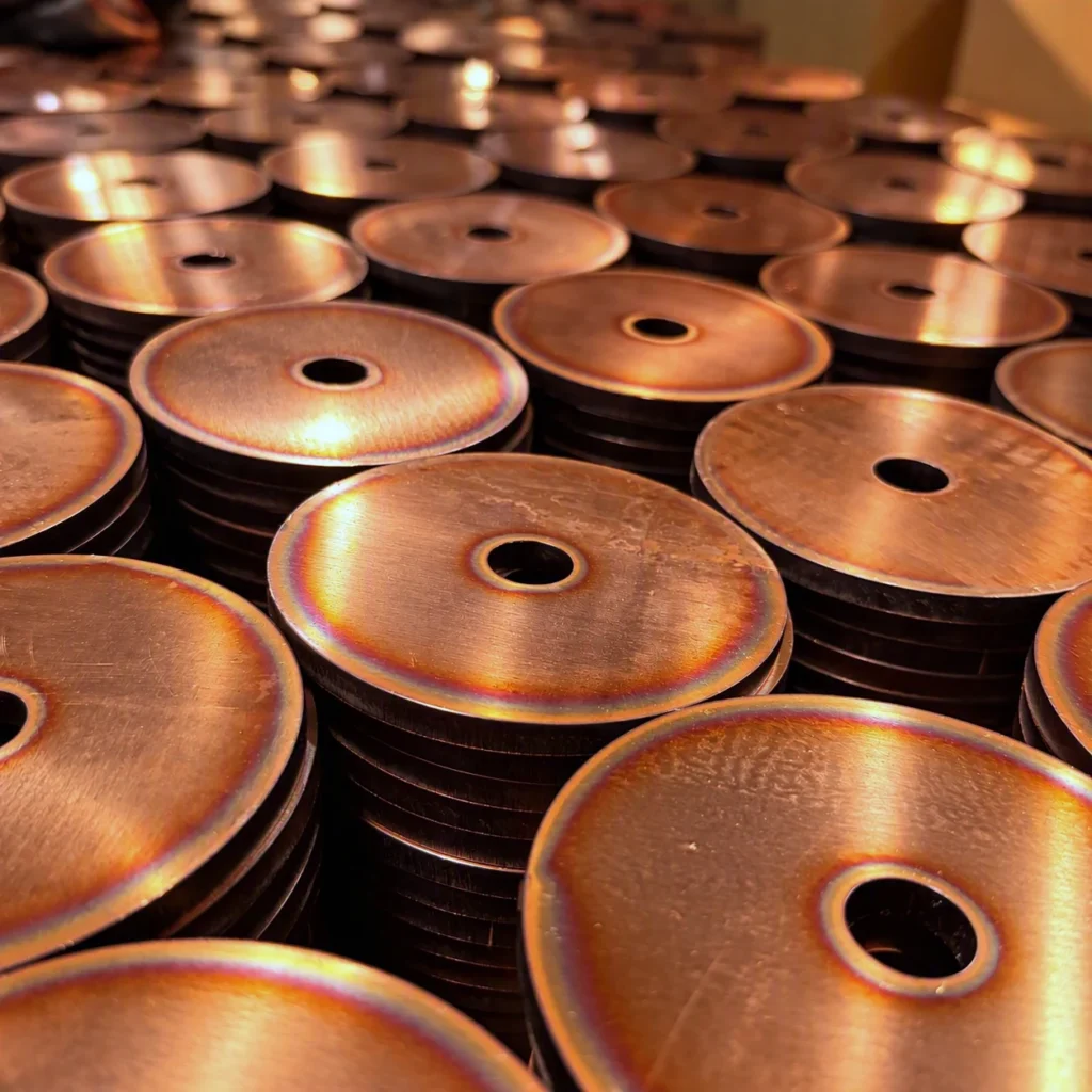
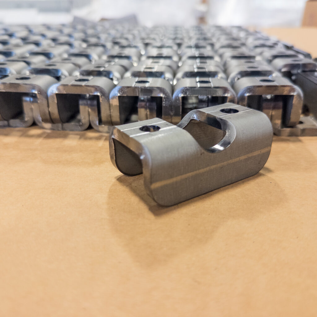
Our design optimization recommendations are based on production experience gained from thousands of fabricated components moving through laser cutting, punching, forming, hardware installation, welding, machining, and assembly operations.
Next, we review all formed features. Bend radii, flange lengths, and material thicknesses must work together. Otherwise, forming operations become unpredictable. We also examine feature locations. Hole patterns, cutouts, and hardware locations must support fabrication processes rather than interfere with them.
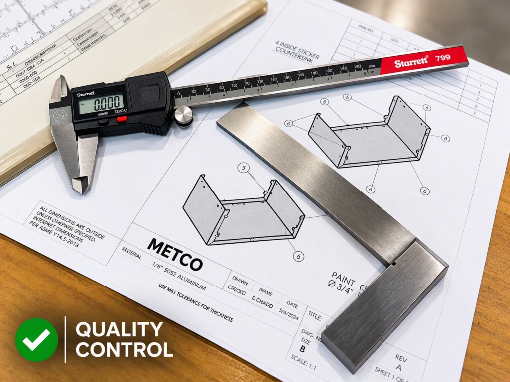
After that, we review tolerances. Tight tolerances increase manufacturing costs whenever they exceed functional requirements.
Finally, we evaluate assembly and welding requirements. Parts that look simple on paper can become difficult to weld or assemble in production.
Tolerance Strategy and Cost Control
Every tolerance carries a price tag.
- ±0.030 $ Standard fabrication
- ±0.015 $$ Additional setup verification
- ±0.005 $$$ Special controls and higher inspection burden
- ±0.001 $$$$ Strictest controls, specialized equipment, and additional processes
Need a Second Opinion on Manufacturing Cost?
Additional inspections, longer setups, and increased scrap potential all contribute to higher costs.
Therefore, engineers should apply precision only where function demands it.
When tolerances match actual performance requirements, production becomes faster and more economical.
The goal is not simply to build the print.
Our engineering analysis process identifies opportunities to reduce manufacturing costs, simplify production, improve assembly performance, and minimize quality risks before production begins. This collaborative approach helps OEMs move from prototype to production more efficiently while maintaining design intent.
Weld Design for Production
Welding often represents one of the largest labor costs in fabrication. Common DFM opportunities include:
- Intermittent welds ($) instead of continuous welds($$) where loading permits
- Plug welds ($) replacing perimeter welds in non-structural attachments
- Single-sided weld access ($) whenever possible
- Self-fixturing tab-and-slot designs (S)
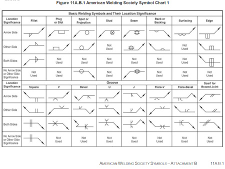
A properly designed joint allows operators to weld efficiently and inspect the finished assembly without difficulty. Small design adjustments often reduce welding labor significantly.
Frequently Asked Questions About Sheet Metal DFM
What is Design for Manufacturability?
Design for Manufacturability, or DFM, is the process of designing parts that can be manufactured efficiently and consistently. DFM considers material selection, bend requirements, hole placement, tolerances, welding, and assembly requirements before production begins.
The goal is to reduce manufacturing complexity while maintaining product performance.
Why is DFM important before requesting a quote?
DFM helps identify manufacturing challenges before they affect pricing and schedules.
Many design issues remain hidden until a fabricator reviews the drawing. Holes near bends, unrealistic tolerances, and poor weld access often increase costs or create delays. A DFM review addresses those concerns before they become expensive production problems.
How does DFM reduce fabrication costs?
DFM reduces costs by eliminating unnecessary manufacturing challenges.
Well-designed parts require less labor, fewer setups, less material waste, and fewer inspections. In addition, manufacturable designs reduce rework and improve production efficiency.
As a result, fabricators can produce parts faster and at a lower overall cost.
Can DFM improve lead times?
Yes.
Manufacturable designs move through production more efficiently because they require fewer engineering clarifications and fewer process adjustments. Consequently, parts spend less time waiting for revisions and more time moving through fabrication. DFM also reduces the risk of production delays caused by design-related issues.
What are the most common sheet metal design mistakes?
The most common mistakes include placing holes too close to bends, specifying unnecessary tight tolerances, selecting incorrect bend radii, creating poor hardware locations, and designing weldments with limited access.
Although these issues may appear minor in CAD, they often increase manufacturing costs and reduce production efficiency.
Does METCO review customer drawings before production?
Yes.
METCO reviews drawings for manufacturability before production whenever possible.
Our team evaluates material selection, bend design, feature locations, tolerances, hardware requirements, welding considerations, and assembly requirements. The goal is to identify opportunities that reduce costs and improve production efficiency before material reaches the shop floor.
We believe the best time to solve manufacturing problems is before production begins, not after parts are already in process.
Need Feedback On Your Drawing?